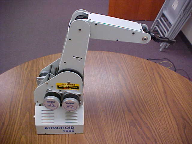


As advertised, the arm came with NO control box or power supply.
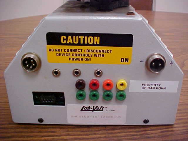
I was hoping that the DB-9 Connected on the back of the arm would hook into a COM port that would then control the robot, but I wanted to double check the circuitry first.

Good thing I checked. At first glance I found the following components on the control board:
- SN75437 - Quad Peripheral Drivers
- 74HCT240 - Octal Buffers and Line Drives
- 74HCT259 - 8-bit addressable latch
- 74HC123 - Dual retriggerable monostable multivibrator
- DS3668 - Quad Fault Protected Peripheral Driver
- MBRF1045 - Schottky Power Rectifier
- 7508 - +5V regulator
- other various components
Since this list did not contain a UART, Microcontroller or Microprocessor, it was obvious to me that the robot was not a COM (RS-232) controlled device.
After downloading all the PDF's for the major components and figuring out what each did, I took to reverse-engineering the circuit.
I had a few false starts reverse-engineering the circuit. For one thing the board was multi-layered (probably 4 layers) so that made it a little more difficult to trace. I ended up ohming out the circuit. This took quite a bit of time, but when I was done I had the following schematic:
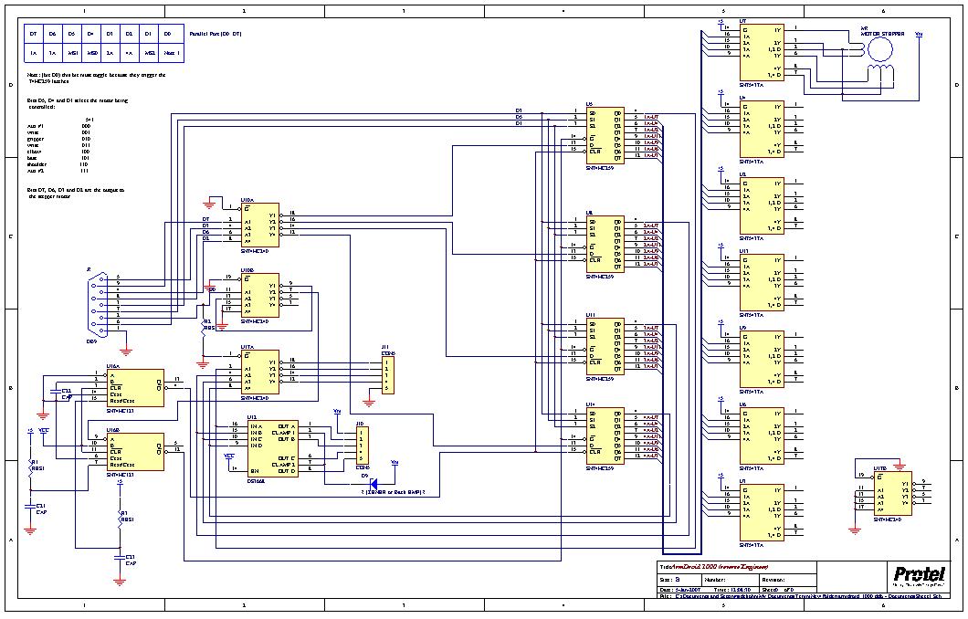
As you can tell, this is NOT a complete schematic, some components are missing (caps, pull up / pull down resistors, etc...)
The power system, also not shown on the schematic, appears to have the power coming in and going though the MBRF1045 then to the 7805 (to supply the IC's with 5V). The voltage coming in seems to be clamped by a Zener Diode at 16V (but, since I could not read the number on the zener, I am NOT 100% sure).
At this point I took a chance and powered up the arm with +12v. It didn't blow up so I started to see what the 74HC123 was doing (this was one section of the circuit I was very unsure of). It seemed like it was being used for a power up reset (U16A) to clear all the HC259's.
Now that I verified that the signals on the DB-9 connector were a logic level and that there were 8 bits being used. I figured that I might be able to use the standard Parallel Port of a PC to connect the arm to a computer. So I made a cable connecting the 8 bits and Ground to the Parallel Port. The wiring is shown below:

Latter I would realize that a straight though cable probably was not the best choice (see below), but at the moment, it allowed me to start to test the circuit.
Now things started to come together. I did verify that part of U16's (the 47HC123) was to act as a power up reset. Also I was able to figure out the table for the input bits. The Armdroid uses 8 bits of data (Coming in on the DB-9 Connector, along with a ground), 3 bits select 1 of 8 outputs (being generated from U7, U4, U2, U13, U9, U6, U3 and U17A/U12). 4 bits are the bit pattern to be sent to the selected motor. The last bit is used as a trigger bit (it must be toggled when the other bits are stable).
| D7 | D6 | D5 | D4 | D3 | D2 | D1 | D0 |
| 1A | 3A | MS1 | MS0 | 2A | 4A | MS2 | Trigger |
| where: | 1A, 2A, 3A, 4A are the stepper motor (coil) outputs MS2, MS1 and MS0 are the Motor Select Bits |
| Motor Select | |||
| Motor | D5 | D4 | D1 |
| Aux #1 | 0 | 0 | 0 |
| Wrist | 0 | 0 | 1 |
| Gripper | 0 | 1 | 0 |
| Wrist | 0 | 1 | 1 |
| Elbow | 1 | 0 | 0 |
| Base | 1 | 0 | 1 |
| Shoulder | 1 | 1 | 0 |
| Aux #2 | 1 | 1 | 1 |
As I stated earlier, maybe a straight though cable was not the best idea since the bits for motor selection and the bits for the stepper motor output are now split and out of order. But, since the cable was built and I was anxious, I did not go back and rewire it, figuring I could do it in software.
Now that I figured out how the motor select works, and which bits are for the actual steps, I wrote the first test program (using EMU8086). After the wiring screw up, I decide to plan the program out a bit so that I could build upon it latter. With this in mind I decided to create the step table so that all the motor select bits and the trigger were all zeros (so the only one's in the table were for the stepper motor itself). I could then use a value (called motor) and set the bits to select the motor and then OR the values together to get the byte to send to the robot arm. Then I would only have to toggle bit zero to trigger the circuitry with the proper time delay in between. I originally had the program using the System Time Interrupt (INT 1Ah AH=00H) and used a loop to delay a specific number of clock ticks, but this turned out to be too slow. So I reverted to a timing loop (that was processor dependant) until I could find something that universally work on all CPUs. Once I figured out the timing, I turned my attention to getting the right bit sequence for proper motor operation. I did this by trial and error and got a sequence that worked smoothly (although an error was found latter on - see below).
After this success, I wrote a second test program. Converting the two routines for the first test programs into subroutines, I then added to the motor drive routine the ability to go though the sequence in BOTH DIRECTIONS based on the status of a flag (this became the DRIVE routine). I then wrote another routine that would allow me to select a motor number (0-7) instead of having to set the D5, D4 and D1 bits each time). This became the MOTOR_NUMBER routine in the program. I then wrote a main to test multiple motor moves. This worked, but I started to hit the current limit of my power supply, but the program did work.
I did some thinking on the current problem and realized that I was leaving the coils of the stepper motor on, so why not just shut off the coils after each move (since I was limited to the power supply I had on hand). So I wrote the third test program and included a MOTOR_OFF routine to do just that. When I tried the program, it was WORSE?!? The current was though the roof even though I was sending 0's to all the stepper motor bits. After mulling this over for some time, it finally came to me that U10A was inverting the signals intended for the stepper motors. So instead of turning off all the coils, I was actually turning them on. After inverting my MOTOR_OFF pattern and my stepper motor table. (The program file here is the pre-fix version).
Now that I figured that out, I wrote a forth program which uses the keyboard for manual control of the robot movements. I intended to use this for demo's at events (let kids play with the arm to attract them to Technology. To make it transportable, I wanted to use an old industrial single board computer I had, but when I went to run the program on it, it didn't work. I then remembered that I used a timing loop for the stepper motor delay so it was CPU dependent. After digging for a while I found a delay interrupt (INT 15H AH=86H) which delays for a given number of microseconds. I rewrote the timing routine and included that in the current version of the program.
When time permits, I hope to do the following:
- Make a program that will remember all the commands performed, do the reverse (to get back "home") and then loop until it is told to stop.
- Make a program that will read a file and perform a pre-programmed series of steps.
UPDATE (8/11/2009)
I really scrapped the ideas above and decided to go a different route. I rewrote the last ASM program in GCC (will post code someday) and am now working on interfacing that program with a PHP Script / HTML Form so that the robot arm can be operated over the internet. I am also adding the ability to calculated the robot position, based on motor steps for each joint, and be able to set limits for the work envelope.
I hope to have the robot arm on the internet soon, so check back often.......
UPDATE (12/??/2014)
The project was taken off line. I hope to work on it again soon an redo the project using a Raspberry PI or simiar controller instead of the old PC used above. Hope to get back to the project this coming summer.
UPDATE (6/18/2015)
A fellow Armdroid hacker (M. Farr) was nice enough to send me a copy of the original manual for the Armdroid and thought I would post it hear. Still hoping to get back to the project and get it up an running again soon.
UPDATE (7/5/2015)
Finally got back to this project. Started working on getting it working on a Raspberry Pi (Model B Rev 1.0 - Rev code 0003)). I am using Raspbian (2015-05-05-raspbian-wheezy.img) image and did the standard install. I then installed the gpio library (found HERE).
Soldered up a DB9 cable with ends from a Female-Female Jumper Wire. Wired it up as follows:
| DB9 Pin | DB9 Wire Color | Female End Color | Function | GPIO Pin |
| 1 | brown | black | gnd | 25 |
| 2 | red | brown | trigger | 11 |
| 3 | orange | red | MS2 | 7 |
| 4 | yellow | orange | 4A | 12 |
| 5 | green | yellow | 2A | 15 |
| 6 | blue | green | MS0 | 22 |
| 7 | purple | blue | MS1 | 18 |
| 8 | grey | violet | 3A | 13 |
| 9 | black | grey | 1A | 16 |
Programming in Python, I got it working with very little trouble (since most of the algorithm is already done in previous versions....just had to convert from the old Parallel port to GPIO of the PI). I did forget that I needed to monitor the current of the powersupply output - since my power supply is a little small for the arm (Max 3.4A @12v), I can only have one stepper on at a time and while developing code it is possible to overheat the power supply if coils are not properly shut off after a move....I have a burnt finger as a reminder). Also found that using single stepping the elbow motor sometimes would jam, so I did double stepping in the code to get it to run reliably.
Also found that the Armdroid is showing it's age. The gripper detached from the hand pivot. It does not prevent me from testing but I need to get it repaired before putting it back on line.
Finished code to drive each motor from the command line using the command:
where:
motor is from the motor select table above (with the addition of 8-11 being for wrist motions).
steps is how far to move
dir (1 or -1) to determine direction of motion.
Code ver 0.1 can be found HERE. This version does not have error trapping and is yet to be commented. I have yet to set up the Pi to serve a webpage and allow for control via the web (that is yet to come, but this shouldn't be too hard since it will be a variation of the previous working version).
last update: 7/5/2015