Since the robot base did have some of the electronics mounted already (see Old Bot Website) I first removed the old HC12 and mounted the Arduino.
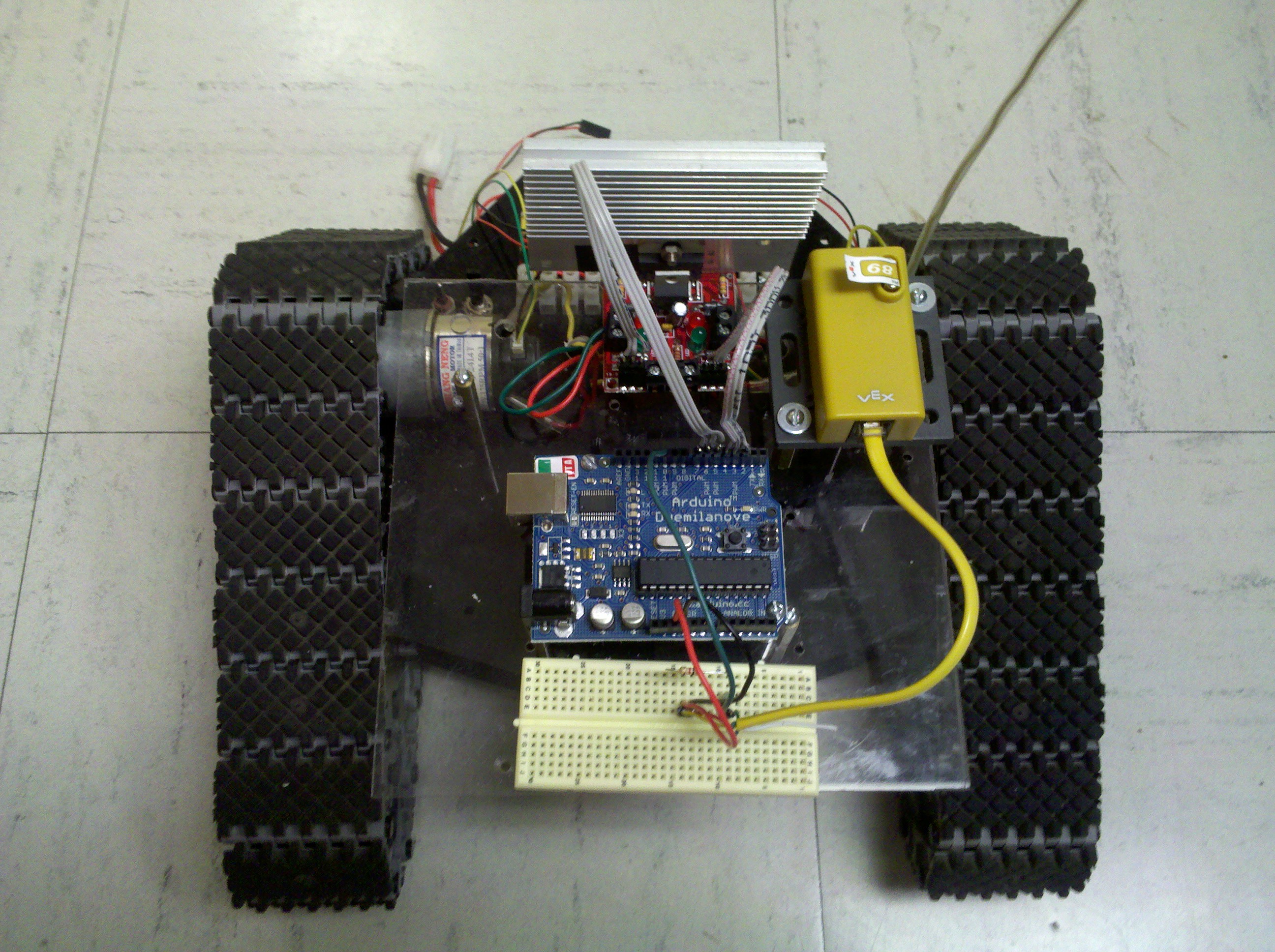
The first thing I wanted to do is to get my VEX Remote Control I purchased years ago working with the Arduino.
I wired the VEX Remote Control Reciever module to the Arduino ( as per the instructions above). I used pin 10 on the Arduino (for the RC modules output and hooked up +5 and gnd. One of the documents (above) mentioned a "Pull Up Resistor" and I did find that I needed a resistor from the signal output to +5v for the RC reciever to properly send the waveform into the Arduino board. Pinouts are as follows (note RED IS GND!):
| Wire | Function |
| RED | GND |
| YELLOW | +5V |
| Green | Signal |
I have no prior experience with the Arduino, but everybody kept raving about it so I thought I would buy one and give it a shot for this project. I found it quite easy to figure out (see Language Reference). For the VEX RC module, I found the pulseIn command was easy to use and was able to read the pulses from the Vex remote control receiver module and return the pulse time (which is a value proportional to the joy stick input). Since the RC module signals look like the following, the PulseIn was a perfect choice to use:

The code to read the RC module first looks for an extended OFF time, then reads the next six off times of the waveform (the On-Times remain a constant for each input, and the Off-Times vary with RC Transmitter possitions).
Here is the
 I wrote to test it.
 Pin 13 is pulsed to indicate an "I'm Alive" status (since that pin is wired to an LED on the Arduino).
I also started wiring the H-Bridge to the Arduino, and hope to actually have the robot move under remote control in the next few days.
10/14/2010
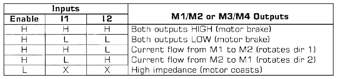
Today I wired the H-Bridge to the Arduino using the following pins:
| Pin | Connection |
| 2 | Enable Left Motor |
| 3 | I2 (I4) Left Motor |
| 4 | I1 (I3) Left Motor |
| 5 | Enable Right Motor |
| 6 | I2 Right Motor |
| 7 | I1 Right Motor |
Where:
Using the 1st test program (from two days ago), I dertimined the following values for the joy stick possition on the RC remote control (channel 1 and channel 2)
| 630 | 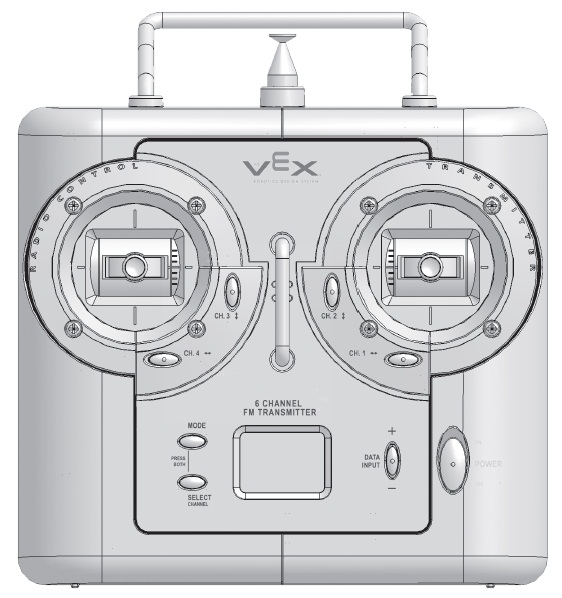 | |||
| ↑ | ||||
| CH1 | 630 | ←1040→ | 1450 | |
| ↓ | ||||
| 1450 | ||||
| CH2 |
I wrote the
to do rudimentary control via the VEX Remote Control.Only have one hitch, when I changed from turning in one direction directly to turning in the other direction, the Ardinio shuts down and needs to be powered down before it will work again. I think this is due to the fact that I am using one 7.4v battery for BOTH the Arduino and the motors, so the back EMF is probably a problem. I am going to try a small pause before direction changes, and if that doesn't work, try a capacitor, then if all else fails, use separate batteries to run the motos.
10/15/2010
Tried a number of program variations to put in the pause, but ran into problems because of the way the program is structured and also because of the way the VEX RC module works. Got something reasonable so that I could demo the robot at the MidSouth Makers meeting tonight. Want to find a more eligant solution to the issue before moving on to the autonomous mode(s).
11/9/2010
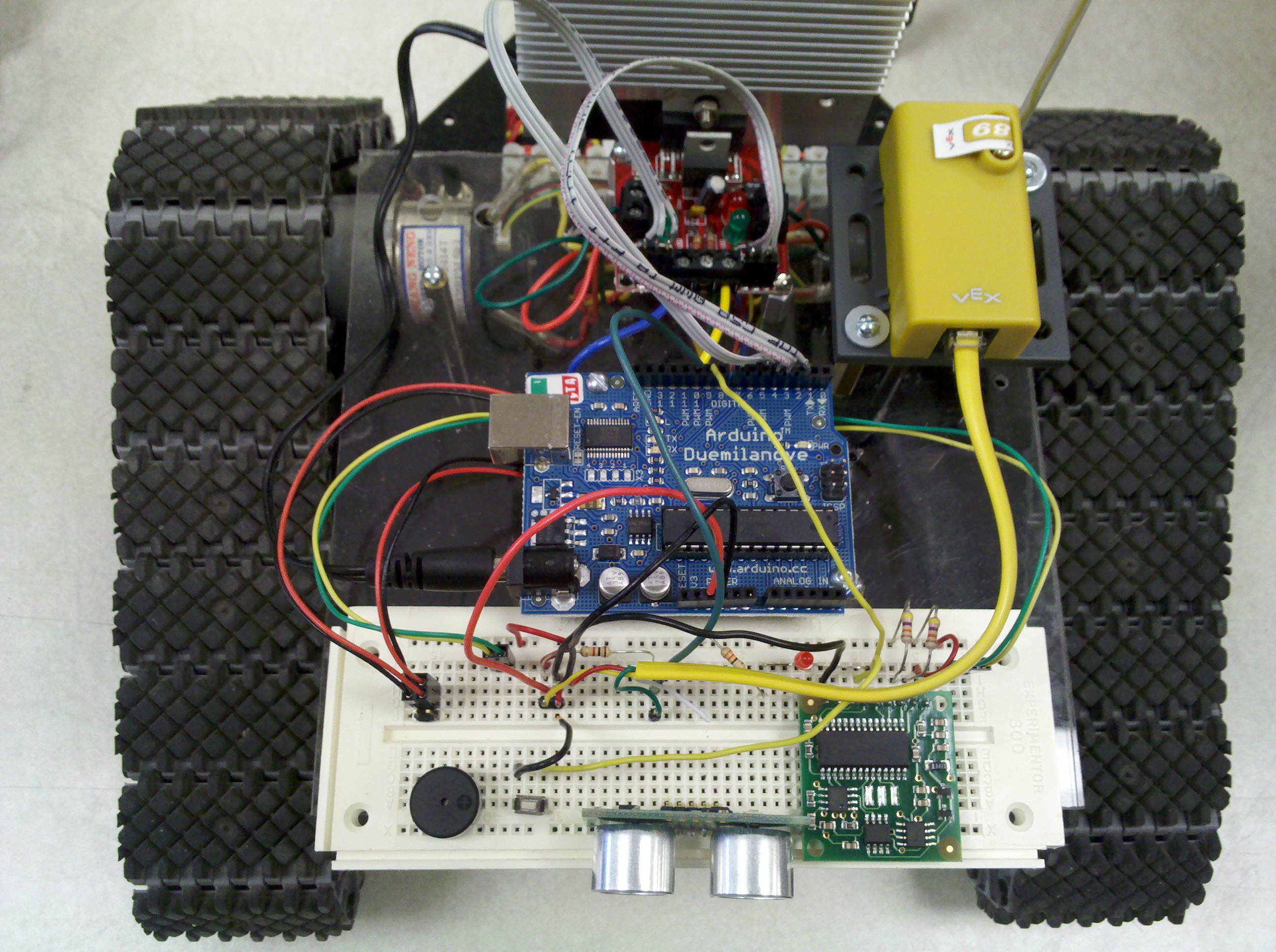
Rewired the bot to add a CMPS03 Digital Compass. Had to replace the protoboard with a bigger one to fit the compass. Made a studpid mistake when I wired back up the remote control. Since RED was GND, I stupidly saw red and said "Oh that's +5 volts". Luckly I have annother reciever, but it was a DUMB mistake (added wire -> function table (above) to avoid that in the future!
Here is some test code for the compass. I wired the PWM out to pin 9 and wired the rest of the compass as per the docs for PWM output (not I2C).
unsigned long compass;

void setup()
{
  pinMode (9, INPUT);
  Serial.begin(9600);
}

void loop()
{

  do
  {
    compass = pulseIn(9,HIGH);
    Serial.print(compass);
    Serial.print("\n");
  }while(1);
}
Then added a SRF05 Sonar Modual to the robot (wired pin 12 as the echo input and pin 13 is the trigger output) and wrote some test code for it as well:
unsigned long starttime;
unsigned long endtime;
unsigned long ttime;
float distance;

void setup()
{
  pinMode (12, INPUT);
  pinMode (13, OUTPUT);
  Serial.begin(9600);
}

void loop()
{

  do
  {
    digitalWrite(13,HIGH);
    starttime=micros();
    delayMicroseconds(10);
    digitalWrite(13,LOW);
    do
    {
    }while(digitalRead(12)!=HIGH);

    do
    {
    }while(digitalRead(12)!=LOW);
    endtime=micros();
    ttime=endtime-starttime;
    distance=ttime*pow(10,-6)*1087*12/2;
    Serial.print(ttime);
    Serial.print(" ");
    Serial.print(distance);
    Serial.print("\n");
  }while(1);
}
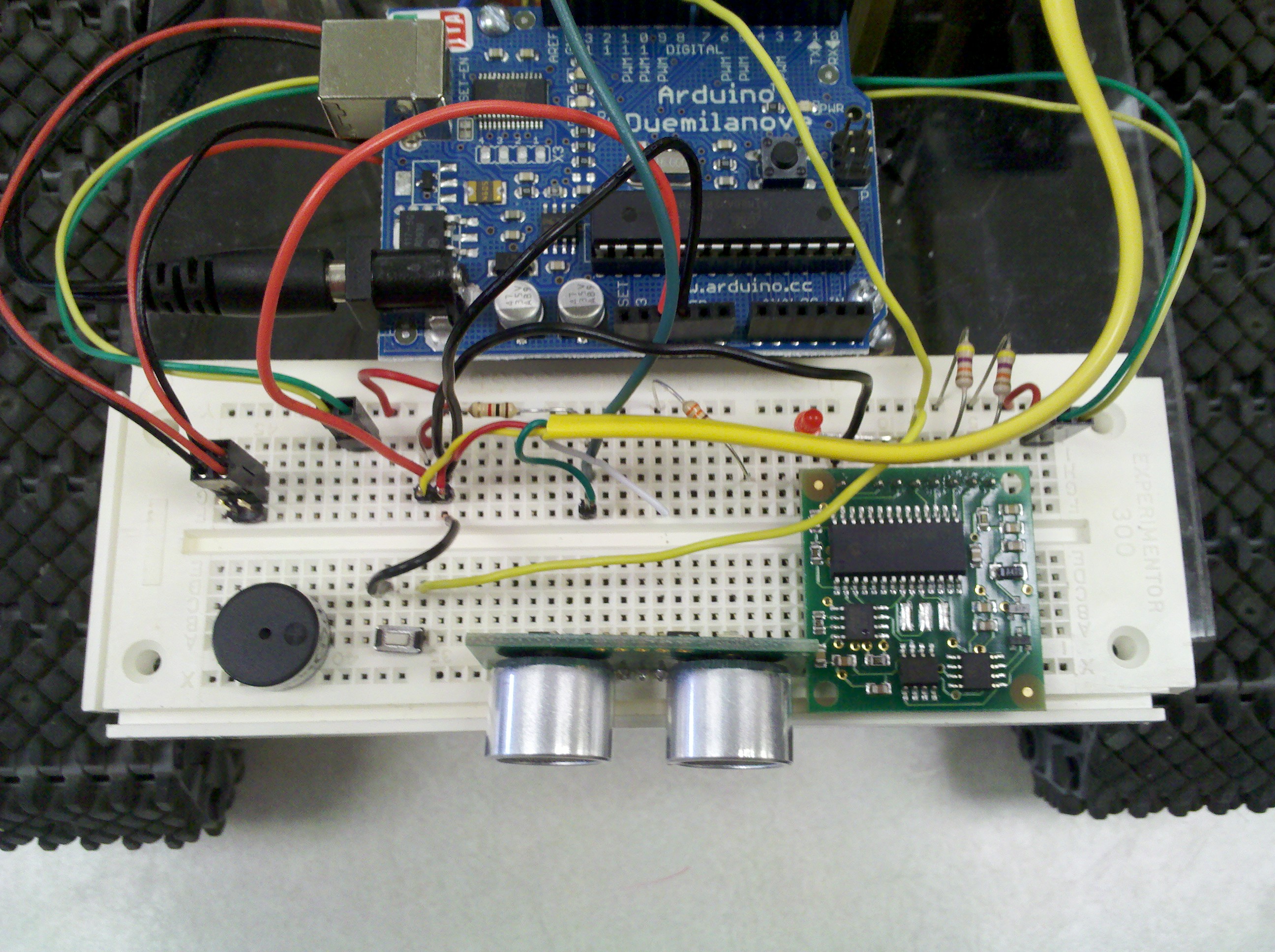
Here are some new pics of the robot:
11/15/2010 to 11/19/2010
Integrated all the above code into one code for E-day on the 19th.
I also made it so that after the Vex RC signal was read, it would toggle two boolean variables if the Channel 5 and 6 buttons were pressed (the buttons on the back of the VEX RC transmitter). This was done with the code below:.
 // handle chn5 and chn6 buttons (set variables chn5 and chn6 (boolean) to true or false
  if (q[5]>1500)
  {
    chn5=LOW;
    mstop();
  }
  else if (q[5]<500)
  {
    chn5=HIGH;
    mstop();
  }

  if (q[6]>1500)
  {
    chn6=LOW;
    mstop();
  }
  else if (q[6]<600)
  {
    chn6=HIGH;
    mstop();
  }
These buttons allow me to put the robot into various modes of operation (since I have two boolean values a total of 4 modes are possible). Mode 0 will be used for RC control, MODE 1 will be for sonar collision avoidance, Mode 2 and Mode 3 I haven't decided yet (but probably various autonomous modes using the Digital compass in some way.
The code underwent a major reorganization from the first RC testcode above. I created subroutines for each motor action (forward, reverse, right, left and stop). I also added the if structure nessisary to perform the various MODEs above. Lastly I added calculations to determine the rate of change of the joystic's possition and the max change (maxerr). The max change would then be used to stop and pause before changing the direction of the robot (to compensate for the change of direction / power down issue reported on 10/14).
The
was completed in time for E-day (but didn't have time to program an automatic mode using the digital compass).
5/9/2011
Now that the semester is over, I can get back to working on my projects. YEA! Added the Proto_Screwshield to the robot. It has been sitting on my desk to be assembled since I bought it about a month ago from AdaFruit.
5/12/2011
Just recieved my Arduino Mega and will replaced the old Arduino Duemilanove with it. Why? The main reason is I want to use the old controller with a EtherSheild and the ScrewShield I purchased for another project and I want the robot to have a faster microcontroller for future expansion.
5/18/2011
Over the past few days I replaced the Uno with the Mega and rewired the bot to the new board. Also reinstalled the compass (which was borrowed by my University of Memphis Hardware (Robotics) team for their bot).
5/21/2011
Really getting a lot done on the robot now. First I defined all pins with names and cleaned up the code while moving it over from the Uno to Mega boards. Got variable speed motor control working, also wired the encoders and programmed interrupts for them as well. I also came up with a much better way to indicate that the remote control signal is not being recieved (and to stop all movement if that is the case).
The latest
.5/23/2011
Here are some updated pics of the robot with the Arduino Mega installed, new LED mode indicator lights (now have up to 7 selectable modes with a clear, so I needed some way of seeing what mode the bot was in) and wiring for the encoders. I also added a test routine to test the compass and encoders as well as a turn to bearing mode (point the joy stick (compass point N, S, E, W) and have the robot turn to that bearing. Still working on perfecting the compass routines (right now the robot has to go way to slow to hit the bearing (with a 5 degree dead band).
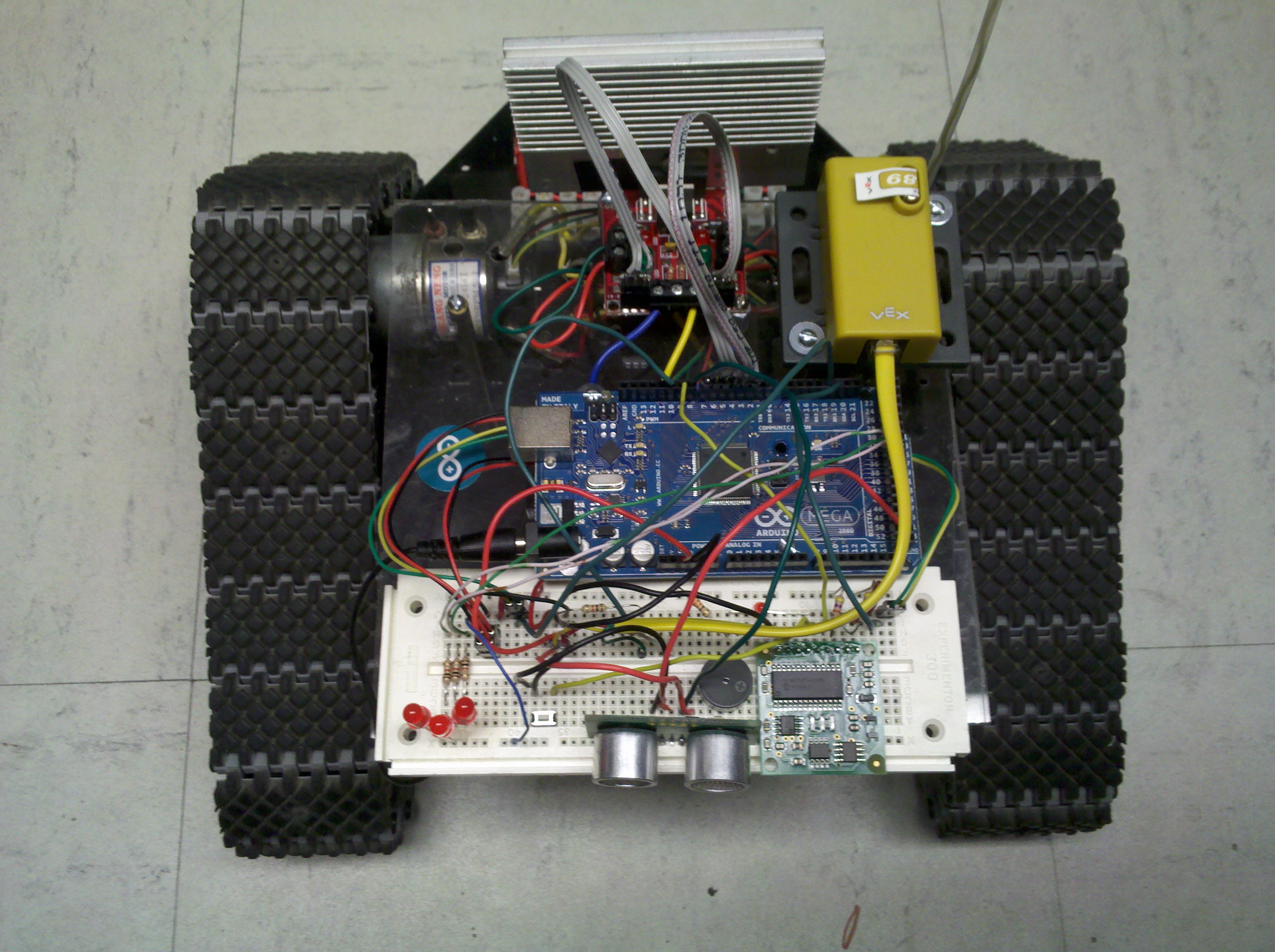
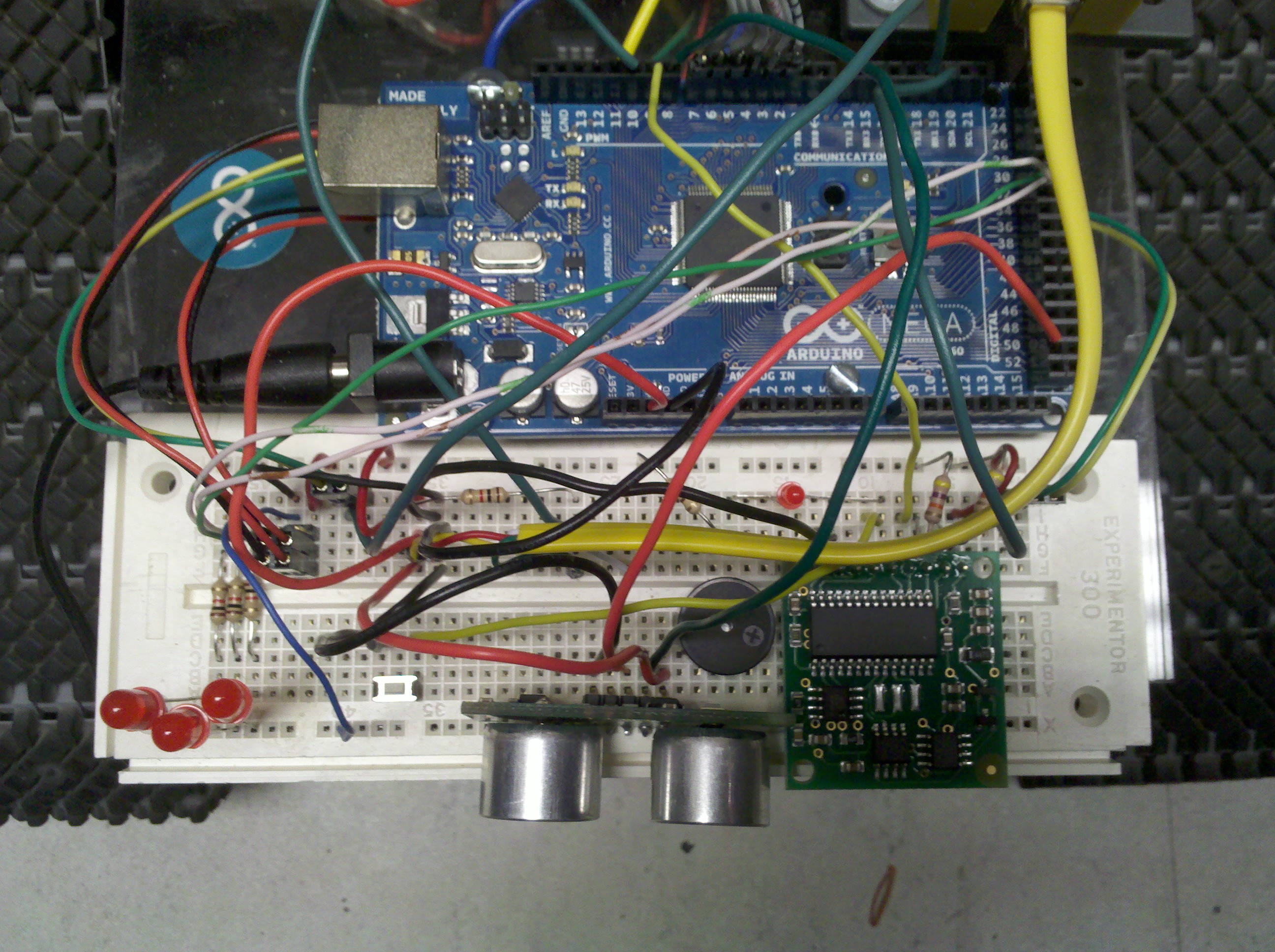
As you can see I am quickly runing out of room to mount stuff on. I might have to add a new plexiglass layer or something. I do want to mount an LCD display (got one and experimented with it on my boarduino) but just cant see how to mount it with the current configuration. Will give it some thought over the next few weeks, but in the meantime the experimentation can continue in its current configuration.
The latest
.5/29/2011
Did some testing on the robot at the MidsouthMakers space yesterday and found that the robot stoped functioning correctly out of doors. Upon investigation, it was found that the robot code would hang in the sonoar did not return an echo. Added code to prevent this occurrence.
The latest
.