|
|
|
We made TOP 5 in semifinals and TOP 8 in finnal at SECON 99!! |
This robot was designed to meet the rules of "A Grand tour of Kentucky." as detailed in the description section. The main difficulties in this competition were to travel in the narrow "streets" of the tour, climb the fifteen degree hill until the end, don't get lost in the dark and unsignalized mine, and make a simple design to complete in only five weeks. Therefore, four factors were important in this design: accuracy in the motor and guidance systems to avoid all the walls, big torque and traction to climb the hill, small size and big weight to open the mine door without lost of control, and use a simple design based in other experiences. To reach these four goals we used the same infrared tracking line and ultrasonic guidance system used the year before, and the Handy Board computer used two years before. However, we designed a new interface to handle two powerful step motors and a powerful electromagnet system of double flux. All this was contained in a new chassis based in aluminum with weight enough to open the mine door without lost of control due to to the torque against the door spring. Hardware-Software The hardware of this robot is composed of eight parts: CPU controller, port extension, ultrasonic range system, electromagnet controller, step motor current amplifier, servo system, tone detector, and IR. tracking line system. The CPU of this robot is a Handy Board (HB) computer based in Motorola HC11. This was programmed in simple ANSI C with the IC compiler that include functions for the HB architecture. The computer is really simple to use and the schematics and PCB assembly are freely distributed by the MIT.
Computer and Extension Board (Click to magnify)
Due to the limited number of outputs of this computer, we had to design an interface extension to allow the control of the two step motors and ultrasonic system. Also was implemented a new version of the ultrasonic range system used the year before in the project R4. In this occasion the ultrasonic system is controlled by the HB computer. See interface and ultrasonic system picture.
Extension Board (Click to magnify)
The electromagnet was designed to pickup the 1/2 inch ball bearing (horse) and place it in the Bluegrass Auction corner. This powerful electromagnet could produce a high intensity flux able to attract the horse from an inch away. The problem was that the high current level heated the coil and produced a dangerous negative discharge voltage level in the switching off. Therefore a design based in two cycles was made. One high flux cycle of 300 ms for the approach and capture of the horse, then a low flux (low current) cycle to transport the horse in 5 seconds to the auction. This was achieved with two current amplifiers in parallel and limiting the current lineally in one of them. In addition, it was added a discharge diode and resistor to handle the negative peak.See PSPICE model schematic.
Electromagnet Controller Model The step motor controller schematic is already showed in the port extension schematic. This controller is connected to eight high gain bipolar transistors in a conventional common emitter configuration through a base current limiter resistor (4 by each motor) . See controller picture.
Stepper Controller (Click to magnify) A servo motor is necessary to control the arm that holds the electromagnet. This arm allows to capture the horse having the robot in motion. The HB computer include a set of functions for servo, so this is connected directly to the CPU and controlled by a simple C function. The servo motor used is an standard medium torque RC model type servo. Just under the servo is an small PCB that holds the tone detector circuit. This circuit is necessary to detect the beep that indicate the beginning of the competition. This is basically composed by an electret microphone with an op-amp audio amplifier and a LM567 tone detector (see National application note). See servo and tone detector picture.
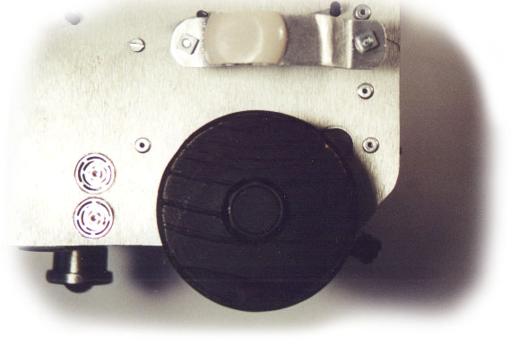
Servo and Tone Detector (Click to magnify) The last hardware module is the IR tracking line system. This is a simple IR transmitter working with a 100mA DC current and two receivers that convert the IR radiation reflected from the white line in a current. This current is converted to voltage using a simple voltage divider and after is amplified by a single bipolar amplifier to TTL logic levels. In the picture we can observe the photo diodes and the potentiometers that limit the current in transmission and reception. This simple circuit is not my favorite idea of a tracking line system, but time and space were decisive to use it design that works only in a very critical manner and requires a tricky and hard calibration.
Detail of the Infrared Tracking Line System (Click to magnify) Mechanics The chassis of this robot is based in a frame made from aluminum angle. This is riveted and covered by an 2 mm aluminum sheet. The motors are two powerful Air Devices step motors with 90 oz-in torque each. Most of the weight is from this motors that have a weight of 17 oz each. The wheels are modeled from a piece of strong red oak wood. A rubber tire is stuck to increase friction. The front wheel is a roll caster used in industrial furniture. Finally, there is a plastic transparent cover made from a pop bottle.
Detail of the Mechanic Motor System (Click to magnify) Finally all the design was made thinking in a easy modular assembly. The up cover and back cover can be easily removed without tools, and the battery replacement can be done quick removing only one cover screw that do not need tools.
Detail of the Mechanic Assembly (Click to magnify)
|